Wire blocks together
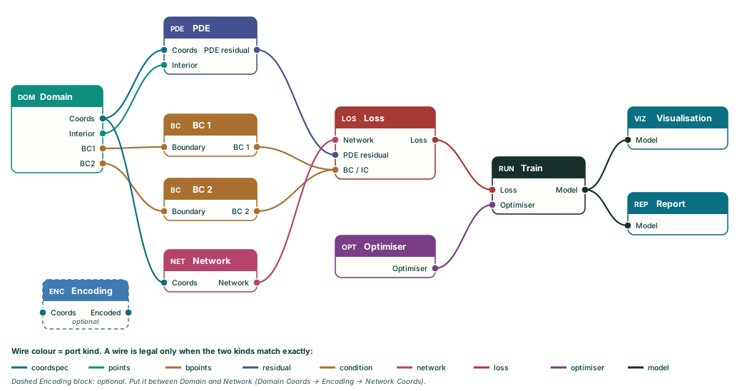
Every connector has a kind, and a wire is legal only between matching kinds. The result is that the Lab will not let you build a wiring the generator cannot use.
Wires carry one thing from one block to another: a set of points, a residual, a loss, a trained model. The studio is strict about what can connect to what, and that strictness is a help: if a wire is accepted, the generator knows what to do with it.
Ports
A block's inputs are on its left edge, and its outputs are on its right edge. Each port is a labelled dot. The dot's colour is the port's kind.
To connect two blocks, press on a dot and drag. A line follows the pointer. While you drag, every port of the same kind on the other side lights up, and those are the only places the wire can end. Release on one. You can start from an output and end on an input, or start from an input and end on an output.
Your screenshot · a wire mid-drag from the Domain's Interior output, with the PDE block's Interior input highlighted.
If you release on a port of a different kind, the studio shows: Those ports carry different things, so they cannot be wired together. Nothing is connected.
The kinds
| Kind | Leaves from | Goes into | What it carries |
|---|---|---|---|
coordspec |
Domain Coords, or Encoding Encoded | PDE Coords, Network Coords, Encoding Coords | The coordinates (x, y, and t if time is on) |
points |
Domain Interior | PDE Interior | Collocation points inside the domain |
bpoints |
Domain BC1, BC2, … | BC Boundary | The points on one boundary |
ipoints |
Domain Initial (only when time is on) | IC Initial | Points on the t = t initial surface |
residual |
PDE PDE residual | Loss PDE residual | The equation error |
condition |
BC and IC outputs | Loss BC / IC | One boundary or initial condition |
network |
Network Network | Loss Network | The trial function |
loss |
Loss Loss | Train Loss | The assembled objective |
optimiser |
Optimiser Optimiser | Train Optimiser | How to minimise it |
model |
Train Model | Visualisation Model, Report Model | The trained model |
One wire or many
Most inputs take one wire. If you drop a second wire onto an input that is already connected, the new wire replaces the old one. That is deliberate: a Network has one set of coordinates, a Train block has one Loss.
Two inputs on the Loss block are different. PDE residual and BC / IC accept many wires. Connect every boundary condition (and the initial condition, if there is one) to the same BC / IC port. The Loss block also takes several PDE residuals if you are solving a system.
Removing a wire
Click the wire. It disappears. Ctrl+Z puts it back.
Ports that appear and disappear
Ports are not fixed; they follow the block's settings.
- The Domain block has one output per boundary that its geometry has. A Line gives two (BC1, BC2), a Rectangle four (BC1 to BC4), a Circle one. Change the geometry and the ports change with it.
- The Domain block gets an Initial output only when its Time dimension box is ticked.
If a setting change removes a port that had a wire on it, the wire is removed too. This is why changing a Rectangle to a Line quietly drops the wires that went to BC3 and BC4. If you change geometry and a wire vanishes, that is the reason.
The order that works
Wire from the Domain outwards, then back in towards Train:
- Domain → PDE: Coords and Interior.
- Domain → each BC (and Domain → IC if there is time): one wire per boundary port.
- Domain → Network: Coords.
- PDE, every BC and IC, and Network → Loss.
- Loss → Train (Loss) and Optimiser → Train (Optimiser).
- Train → Visualisation and Train → Report, if you want plots and a table.
An Encoding block is optional. If you use one, put it between the Domain and the Network: Domain Coords into Encoding Coords, Encoding Encoded into Network Coords.
Every block you want in the script needs a path that ends at the Train block. A block without one is ignored. If you place more than one Train block, only the first is used.